
I will show you how we 3D print our own custom 1:12 scale weapons in this how-to article. You can follow along and learn how to do it yourself with your own 3D printer. This will save you money in the long run, and you’ll have the ability to make new weapons on demand.
3D printers have given us the flexibility to make prototypes on the fly. Although our custom weapons are injection molded, we 3D print them initially for testing and fitting before making the aluminum mold in our CNC machine. This ensures the weapons are within the expected size, scale, and fit before the mold is made. This helps us avoid the costly mistakes of making a mold that contains defects.
If you ever wonder how much it costs to make a custom mold, read my previous article here (“Why do custom GI JOE weapons and accessories cost so much?”). It will give you a nail-biting idea of why some 3rd party vendors avoid it.
Before we begin, please be aware that this article is not a guide to using a 3D printer. Therefore, I assume you already possess beyond basic knowledge and experience in 3D printing. I also think that you have your own 3D printer, slicing software, and 3D editing software.
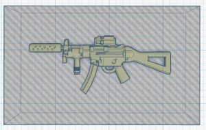
We will refer to the AnyCubic Photon as the 3D printer throughout this guide. We will also refer to TINKERCAD as the 3D editing software and Chitubox as the slicing software. And to make things easier to follow, we will refer to our Custom Tactical Combat Sub Machine Gun SMG as the example model. The Tactical Combat SMG was released for sale on 5-16-2022. On our eBay store, you can purchase the sturdier, injection-molded version of this VERY COOL accessory.
It is not a requirement for you to have the exact same machine, software, and 3D model I mention in this guide. The concept should be similar whether you’re using a different device, software, or 3D model. Therefore, you should be able to follow along and apply what you learn later.
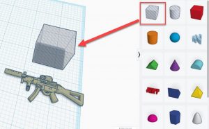
Now that those are out of the way let’s get printing. The first step is to load the 3D model into TINKERCAD.
STEP #1 – Load 3D Model onto TINKERCAD
If you haven’t already done so, download the 3D model we will use throughout this guide. It’s our Custom Tactical Combat SMG, and you can download it here.
We use TINKERCAD as our 3D editing software. It is FREE and more than enough for what we need in the shop. Again, you’re not required to have TINKERCAD. Feel free to use your own.
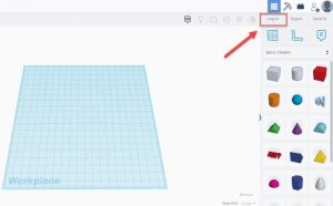
In the upper-right-hand corner of the TINKERCAD workspace, click on “Import.”
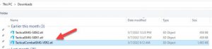
Click “Choose a File” on the next window, then browse to the location of where you downloaded the 3D model and double-click the file.

This will bring up the Import confirmation window in TINKERCAD, as shown here.

Leave everything in their default values, and click the “IMPORT” button at the bottom to import the model.
Depending on the file size of the 3D model you’re trying to import, it could take a few minutes to load. You should see a message on the lower left-hand corner of TINKERCAD informing you that the model is trying to load. It should look like this:

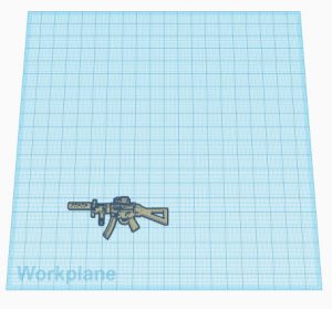
Once the loading has finished, the 3D model of the Custom Tactical Combat SMG weapon should be on the workplane like this:
Great! You now have the 3D model on the workplane, and we can begin editing it to prepare for printing.
STEP #2 – Edit 3D Model for Printing
I like to “split” the model into 2 halves and print both sides simultaneously. I like this technique because it saves me a lot of printing time and avoids ruining one side of the model’s surface from the supports.
Using print supports is beyond the scope of this guide. Still, I would suggest avoiding placing them on any of the guns’ largest surface areas. Most of the gun’s details, like the magazine release button, switches, toggles, etc., are usually on the weapon’s sides.
Let’s make the “split.” It is straightforward to do in TINKERCAD.
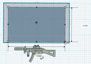
To the right of the workplane, you’ll see the basic shapes available for use in TINKERCAD. Drag a “hole-box” onto the workplane, as shown here.
Increase the Length and Width of the hole box (the box you just placed onto the workplane) by dragging one of its size controls on the corner. You don’t need it to be a specific size, but you just need it to be larger than the Tactical Combat SMG. The gun is 2.53 inches x 1.04 inches (LxW), so anything larger than this will work.
Next, we will need to lower the hole box below the workplane and the Combat SMG halfway through.
Single-click the hole box to bring up its controls. You’ll need to look for the Raise/Lower control, which should look like a “CONE,” like here.
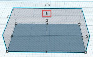
Click and hold the Raise/Lower control and drag it down to lower the hole box. The moment you start to do that, you’ll notice some numbers flicker towards the bottom right corner. This is the distance indicator and tells you the distance (in inches) how far you’ve raised or lowered the box.
In this sample screenshot, you can see that I’ve lowered the box approximately 0.2 inches below the workplane since the value is a negative number (-0.218). A negative number means “below,” and a positive number means “above.”
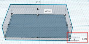
We want the box’s top surface to be “level” and “flush” with the TINKERCAD workplane. Since it is 1 inch thick by default, we need to “lower” the box by 1 inch.
Simply grab the “cone-shaped” Raise/Lower control, drag it down to lower it, and wait for the distance indicator. Once it shows up, click inside the textbox, delete the value, type in “1” (for 1 inch), and press ENTER on your keyboard. This will automatically lower the box by precisely 1 inch. And the box’s top surface will be flushed and leveled with the TINKERCAD workplane (which is what we want).

We need to do the same thing for the Combat SMG, except it only needs to be lowered halfway this time. So, let’s do that now.
Position the Combat SMG model centered over the hole box. It doesn’t have to be perfect, but the gun needs to be inside the box’s parameters, as seen here.
Once again, grab the Raise/Lower control and drag it down until the distance indicator shows up. Once it does, click inside the textbox, delete the contents, and type in “-0.11,” noting the negative sign in front.
This will automatically put the Combat SMG halfway below the workplane. When you look at the gun from the FRONT view in TINKERCAD, it should look similar to this:
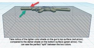
Note that the top surface has a lighter shade color than the one on the bottom.
It’s time to “split” the two halves. Let’s do that by single-clicking on the hole box (you’ll know it has been selected when you see the size controls show up). Then, press “SHIFT” on your keyboard, and finally, single-clicking on the Tactical Combat SMG.
This will select both objects, and your workplane should now look like the image shown below. Take note of the “Shapes” window on the right-hand side. It should show that 2 shapes have been selected.
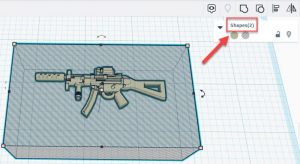
Once both are selected, click on the “GROUP” button to group the two objects together. TINKERCAD will automatically slice and “delete” the lower half of the Tactical Combat SMG. You’ll be left with the other half on the workplane.

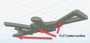
You can verify your work by rotating the view in TINKERCAD to the BOTTOM view. You’ll notice that the Tactical Combat SMG has a missing half. You’ll also see that the bottom surface is flat and flushed to the top of the workplane. It should look similar to the image below:
All we need to do now is make a mirrored copy of the first half of the gun and use it as the second half. Take a close look at your weapon and ensure that both side surfaces are the same. If not, you will have to do the same steps mentioned above for both halves. Taking a mirrored copy of one-half of the weapon will only work if it has identical sides.
For the Tactical Combat SMG, the surfaces on the sides are identical. So, we will take the first half, mirror it, and create our second half. It is effortless to do in TINKERCAD.
Click on the weapon to select it, and click on the “Duplicate and Repeat” button in the upper left-hand corner. As the button’s name suggests, this will create a “copy” of your selected model.
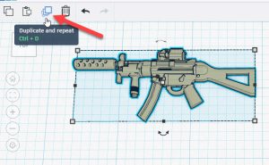
After clicking on “Duplicate and Repeat,” click on one of the models to select it. It may appear tricky at first because both model halves are on top of each other. However, if you drag one of the halves over to the right or left, you’ll see that there are, in fact, 2 of the same models.
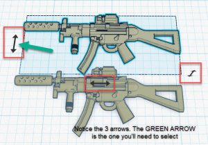
Go ahead and do that. Drag one over to either side. While you already have it selected, click the “Mirror” button on the upper right corner, as shown in the picture below.

Once you click the “Mirror” button, you’ll be presented with 3 arrows. This is TINKERCAD asking you which way you would like the object to be “mirrored.” When looking from the top view, we want to mirror or flip the object on its Y-Axis. You’ll want to select the set of arrows on the left side, like the one shown in the image below.
Now that the 2 halves are done position them on the workplane to make it easier for you to print them. There’s really no right or wrong way to do this, but rather it’s a personal preference. You just need to make sure that the combined dimensions of the 2 halves are small enough to fit inside the size of your print bed. I like to position mine like this:
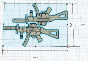
This is what I was referring to earlier. Notice that if you select both halves simultaneously (like the way it is in the picture), TINKERCAD will give you the rectangular dimensions of the 2 objects combined. Just make sure that the numbers are small enough to fit inside your printer bed. Mine is at 2.9 inches x 2 inches, and my AnyCubic Photon’s print bed is big enough to print them.
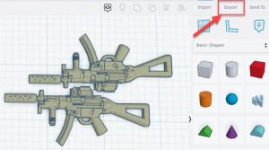
Now that our 2 halves are on the workplane and positioned exactly the way we want, the last thing we need to do in TINKERCAD is to export the model.
Click on the ‘Export” button in the upper right-hand corner to start the process.
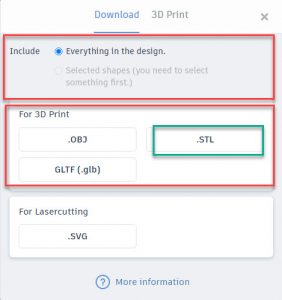
The Download window will pop up. Make sure that the “Everything in the design” option is selected under the “Include” section, and then click on “STL” in the “For 3D Print” section.
This will initiate the downloading process, and depending on the size of your model, it can take a few seconds to complete. Once the download is finished, you can exit out of TINKERCAD, and you are ready to slice the object with your slicing software.
STEP #3 – Slicing
Great job! You’re one step away from printing your custom 1:12 scale Tactical Combat SMG. Open up your slicing software and load the STL file you just downloaded from TINKERCAD earlier.
We use Chitubox as our slicing software for the shop. Again, it’s FREE, and it’s more than enough for what we need. Chitubox has a paid version, which offers more advanced features. It might be worth checking out if you think you’ll need more advanced features for your prints later on.
In Chitubox, click on “Open File,” located in the upper left corner, which should bring up the open file window.
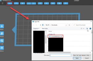
Navigate to the location where you downloaded the STL file for the Combat SMG (there’s a good chance it’s in your Download folder).
Wait for the 2 halves to show up on the Chitubox interface.
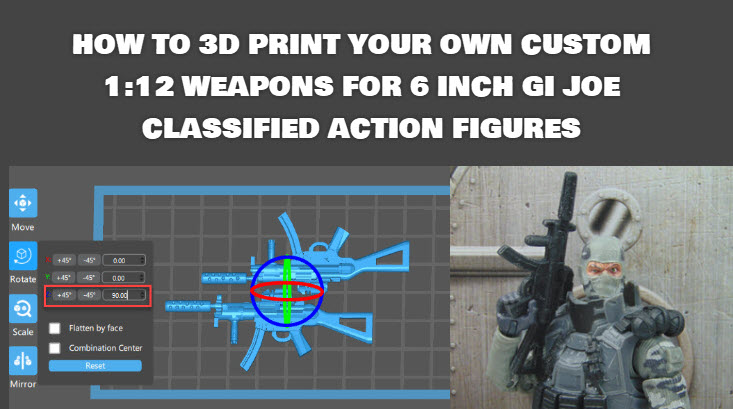
Depending on how you positioned the model earlier in TINKERCAD, it may be necessary to rotate them so that they will fit inside the print bed. If your model looks like this when the model loads:
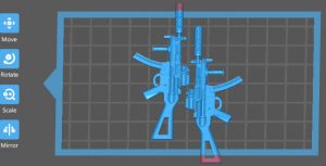
You will need to rotate it. Simply click on the “Rotate” button on the left-hand side to bring up the Rotate menu. You will need to change the Z-AXIS value and give it 90.00 degrees to rotate to the left.
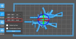
As you can see, the Custom Tactical Combat SMG fits nicely inside the print bed. The only thing left to do now is slice the model to generate and export the file needed for your 3D printer.
Click on the little arrow on the left-hand side of the “Slice” button to select the printer configuration you want to use. After that, simply click on “Slice,” and Chitubox will do its magic.
PLEASE NOTE:
Setting up Chitubox and configuring your printer is well beyond the scope of this article. There are plenty of how-to articles and guides on setting it up if you need help. You can also search on YouTube, and I am sure there’s something that will be useful for you.
If you are using the AnyCubic Photon 3D Printer and would like to know the configuration we use for Chitubox, please let us know and send us a message here. We will be more than happy to help you out and share our settings.
After the slicing operation, Chitubox will present you with the print details. It will show you the amount of resin it will take to do the job. The approximate overall price (based on settings and configurations) and, most importantly, the total time it will take to complete the print.
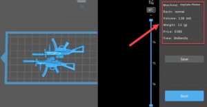
Pretty cool, right?
If all looks good to your liking, click on SAVE. This will make Chitubox create and export the file needed to print the model in your 3D printer.
The only thing left to do now is to PRINT!
STEP #4 – 3D print the model
The time has finally come to print the Custom Tactical Combat SMG!
Flip the switch to turn on your 3D printer and load the file Chitubox exported for you in the previous step. If you use the AnyCubic Photon 3D printer, you should save the file into a USB drive. Plug it into the machine, and when you’re ready to print, the model should show up in the Print menu as one of the available models for print.
Using the AnyCubic Photon, it should look like this:

Verify that it’s the correct model, and select “PRINT.” In AnyCubic, it’s the “PLAY” button on the screen.

The print should take roughly 40 to 60 minutes to complete. However, depending on the settings and configurations you have in Chitubox, it could take longer.
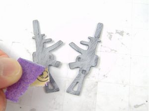
Once the job is done, use your scraping tool to carefully remove the prints off your print bed. Dunk them in an IPA bath (or mild soap and water can work too) and then let them dry. Then, cure the two halves inside a UV curing chamber or your own UV curing light source.
After they cure, it’s time to glue the two halves together.
I like to rough up the surfaces of the pieces I am about to glue. This helps create a stronger bond between the 2 halves, and the glue dries quicker, in my opinion.
Take both halves and flip them over so that their flat faces (bottom side) face up. Take a small piece of sandpaper (it doesn’t really matter how fine they are) and gently sand the flat faces down. Use small circular motions and sand down the entire area for both sides.
We like to use Loctite Gel Superglue for gluing the 2 halves together, but feel free to use any adhesive you see fit. Apply a small amount of super glue on the roughed-up surfaces, align them accordingly, and press them together tightly with your fingers or tweezers. Try not to squeeze too hard because they can snap and break.
Once the glue dries, you are done!
Congratulations!
You have 3D printed your own 1:12 scale weapon!
CONCLUSION
I hope you found this how-to-guide helpful. I hope it sheds some light on how to print your own custom 1:12 weapons and accessories. For the most part, if the weapon or accessory can be split in half right down the middle, you should be able to print it without much trouble.
If you want to take it further, you can post-process the printed weapon and detail it. Apply some primer and model paint for a more realistic look! You will have to dig around for a tutorial on how to do that, but I am sure there are folks on Youtube that show how to paint minis.
If you already 3D Print custom 1/12 weapons and accessories, and want to make some extra cash, I invite you to visit Dio Props 4 Hire. It’s a unique classified ads that caters to the miniatures and diorama community. Once you register for a FREE account, you can post ads to offer your talent and skills to the community. Ads are only $5.00 per post to any category, except for gigs. Ads posted to the gigs category are only $2.00 per post. You can’t beat the price!
A unique feature Dio Props 4 Hire has to offer is that it’s targeted for a very specific niche. Because of that, most (if not, all) of the visitors on the site will be a miniature/diorama enthusiast just like you.
In other words, it’ll be easier to sell what you have to offer because there’s an instant connection. People looking for someone to 3D Print them a custom 1/12 scale weapon for their GI JOE Classified figures are “intentionally” looking for that.
As a proud sponsor of Dio Props 4 Hire, I look forward seeing you there. If you have any questions or concerns, please send me a message here.
What other topics or tutorials would you like to see on the Mini Arms Depot (MAD) Blog? We welcome your feedback and would like to hear from you. Send your requests here.